Loop real-time

By accessing real time whilst in the programming section of a loop, the software asks whether access is required to real-time display of the statuses of the devices on the entire loop or just for one device
By selecting the display of the loop status, the software connects directly to the system and shows the statuses of the devices it comprises indicated by the colour of the relative strings or icons:
|
|
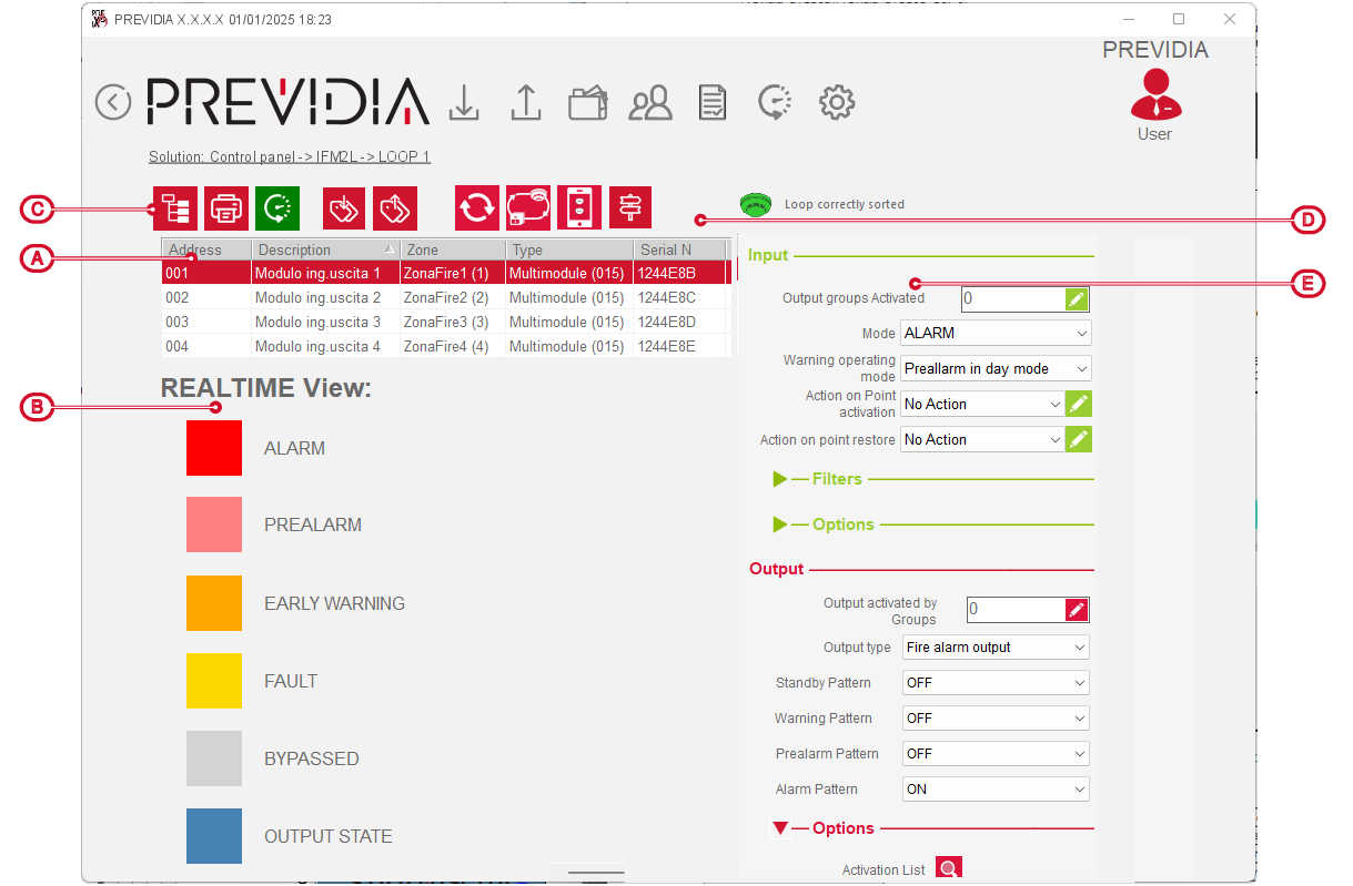
The status of each device is indicated by a specific colour, as shown in the caption on the left, and results from the activation of the signals of the point itself.
In the event of activation of multiple signals from the same point, the priority is as follows:
|
1 |
ALARM |
Activation of alarm, evacuation or extinction signals |
|
2 |
PREALARM |
Activation of pre-alarm signals |
|
3 |
EARLY WARNING |
Activation of alarm early-warning signals |
|
4 |
FAULT |
Activation of fault or supervision signals |
|
7 |
BYPASSED |
Device disabled |
|
8 |
OUTPUT STATUS |
Device output activated |
|
8 |
STAND-BY |
Normal operating status of the device |

This section allows you to consult the order of the loop device addresses via the icon next to the function keys [D] and their colour:
-
green – loop in correct order, having devices with progressive and continuous addresses
-
yellow – loop with devices with non-consecutive addresses
-
red – loop with points from which branches start (T-junctions)